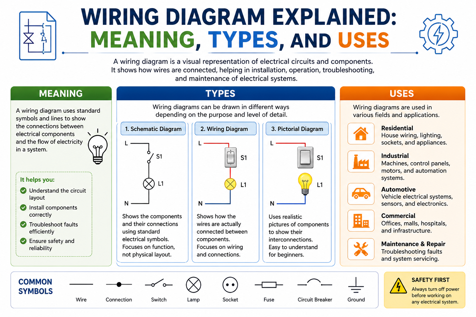
A wiring diagram is a detailed visual representation that shows how electrical components are connected within a system and how electricity flows between them. It works like a structured map for electrical circuits, allowing engineers, electricians, technicians, and even DIY users to understand the exact arrangement of wires, switches, devices, and power sources. Instead of guessing how a system is connected internally, a wiring diagram provides a clear and standardized illustration of every connection point, making complex systems easier to design, install, and maintain.
At its core, a wiring diagram is not just a drawing but a technical communication tool. It translates complicated electrical structures into simple symbols and lines that represent real-world components. For example, a light switch, a power source, or a motor is not drawn realistically but represented through standardized symbols. These symbols help maintain clarity across different industries and countries, ensuring that anyone trained in reading diagrams can understand them without confusion.
Wiring diagrams are used in everything from small household electrical systems to large industrial installations and advanced IT infrastructure. Whether it is a simple home lighting setup or a complex server network in a data center, wiring diagrams act as the foundation for proper system organization. They help ensure that every connection is correctly placed and that the entire system functions safely and efficiently.
Understanding the Purpose of Wiring Diagrams
The primary purpose of a wiring diagram is to provide clarity about how a system is structured and how its electrical components interact. Electrical systems can become extremely complicated when multiple devices, circuits, and power sources are involved. Without a diagram, it becomes difficult to trace connections or understand how power moves through the system. A wiring diagram solves this problem by offering a simplified visual layout that represents the entire structure in an organized way.
Another important purpose of wiring diagrams is to eliminate guesswork during installation and maintenance. When technicians work on electrical systems, they rely on these diagrams to ensure that every wire is connected to the correct point. This reduces the risk of mistakes that could lead to system failures or safety hazards. In many industries, following a wiring diagram is a standard requirement before starting any electrical work.
Wiring diagrams also play a key role in planning new systems. Engineers use them during the design phase to test ideas and ensure that the proposed setup will work properly before actual installation begins. This helps prevent costly errors and allows adjustments to be made early in the planning process.
How Wiring Diagrams Represent Electrical Systems
Wiring diagrams represent electrical systems using a combination of standardized symbols, connecting lines, and structured layouts. Each symbol stands for a specific component, such as a resistor, switch, relay, or power source. These symbols are universally recognized in the electrical and engineering fields, which allows diagrams to be understood regardless of language or region.
The lines in a wiring diagram are equally important because they represent electrical connections. These lines show how electricity travels from one component to another. A straight solid line often indicates a direct connection, while different line styles may represent alternative paths, control signals, or special types of connections. This visual system makes it easier to follow the flow of electricity through a circuit step by step.
The layout of a wiring diagram is carefully structured to ensure readability. Components are arranged in a logical manner, often following the direction of electrical flow or system hierarchy. This organized structure helps users trace connections easily without getting lost in complexity. Unlike physical installation layouts, wiring diagrams focus on clarity rather than physical placement, which means components are arranged in a way that best explains the system rather than where they are physically located.
Importance of Wiring Diagrams in Modern Infrastructure
In modern infrastructure, wiring diagrams have become essential tools for building and maintaining electrical and digital systems. As technology continues to advance, systems are becoming more interconnected and complex. From smart homes to cloud data centers, almost every modern system relies on electrical and network connections that must be carefully designed and managed. Wiring diagrams provide the foundation for this organization.
In IT environments, for example, wiring diagrams are used to map out network connections between servers, switches, routers, and other devices. Without a clear diagram, managing such systems would be extremely difficult, especially when troubleshooting issues or upgrading equipment. These diagrams help IT professionals understand how data flows through a network and where potential bottlenecks or failures may occur.
In industrial environments, wiring diagrams help manage machinery, control systems, and power distribution networks. Large facilities depend on accurate diagrams to ensure that equipment operates safely and efficiently. Even a small wiring mistake in such environments can lead to serious operational issues, making diagrams an essential part of system reliability.
Role of Wiring Diagrams in Electrical Safety
Electrical safety is one of the most critical reasons wiring diagrams are used. Electricity can be dangerous if not handled correctly, and improper wiring can lead to short circuits, equipment damage, or even fire hazards. Wiring diagrams reduce these risks by providing a clear and accurate guide for proper connections.
When technicians follow a wiring diagram, they are less likely to make incorrect connections or overlook important safety components such as fuses, breakers, or grounding points. These safety elements are clearly represented in diagrams, ensuring they are included in the system during installation.
Wiring diagrams also help in identifying potential safety issues during inspection and maintenance. If a system is not functioning correctly, technicians can compare the physical wiring with the diagram to quickly locate errors or damaged connections. This makes troubleshooting faster and safer, especially in high-voltage or sensitive environments.
Wiring Diagrams in Everyday Technology and IT Systems
Wiring diagrams are not limited to industrial or engineering environments; they are also deeply connected to everyday technology. Modern homes, offices, and digital systems all rely on structured wiring to function properly. Devices such as internet routers, smart TVs, security systems, and home automation systems all depend on properly designed wiring layouts.
In IT systems, wiring diagrams are especially important because they help manage the flow of data as well as power. Network setups often involve multiple layers of connections, including local area networks, wide area networks, and wireless systems. A wiring diagram helps visualize how all these components interact, making it easier to maintain performance and reliability.
Even in simple setups like home internet connections, wiring diagrams help users understand how modems, routers, and devices are connected. This makes it easier to set up new systems, upgrade equipment, or fix connectivity issues without confusion.
Why Professionals Depend on Wiring Diagrams
Professionals across different fields depend heavily on wiring diagrams because they provide accuracy, consistency, and efficiency in working with electrical systems. For electricians, these diagrams are essential during installation work, as they guide every connection from start to finish. Without them, installation would be slow, error-prone, and potentially unsafe.
Engineers use wiring diagrams during the design and development of new systems. They help simulate how a system will behave before it is physically built. This allows for improvements and corrections early in the process, saving time and resources.
Technicians rely on wiring diagrams during maintenance and troubleshooting tasks. When a system fails, the diagram becomes a reference point for identifying where the issue might be occurring. By tracing connections step by step, technicians can quickly isolate and resolve problems.
In IT and networking environments, professionals use wiring diagrams to manage complex infrastructures. These systems often include hundreds or even thousands of interconnected devices. A well-designed wiring diagram ensures that everything remains organized and manageable, even as systems grow in size and complexity.
What is a Wiring Diagram?
A wiring diagram continues to play a vital role in understanding how electrical and electronic systems are structured, especially when systems become more advanced and interconnected. In the second part of this discussion, the focus shifts toward deeper functional understanding, real-world usage patterns, and how wiring diagrams support both technical accuracy and long-term system management. As technology expands into every aspect of modern life, the importance of clearly documented electrical connections becomes even more significant. Wiring diagrams are no longer just tools for electricians; they are essential blueprints for engineers, IT professionals, system designers, and maintenance teams across multiple industries.
The Functional Logic Behind Wiring Diagrams
Wiring diagrams are built on logical representation rather than physical appearance. This means they do not attempt to show exactly how wires are physically routed in real space. Instead, they focus on how electrical signals or power move through a system. This logical approach allows complex systems to be simplified into readable structures that anyone trained in electrical principles can understand.
The main function of a wiring diagram is to show relationships between components. Each connection represents a path for electrical current or data flow, depending on the system type. By following these paths, users can understand how input signals are processed, how power is distributed, and how outputs are generated. This logical mapping is especially important in systems where multiple circuits operate simultaneously, such as industrial machines or computer networks.
Another important functional aspect is system traceability. Wiring diagrams allow users to trace the complete journey of electricity or signals from the source to the final output device. This makes it possible to identify where a fault might occur, how different components interact, and what role each part plays in the overall system. Without this logical structure, troubleshooting would be slow, inefficient, and highly error-prone.
Role of Standardization in Wiring Diagrams
One of the key strengths of wiring diagrams is their reliance on standardized symbols and conventions. These standards ensure that diagrams can be understood universally, regardless of language or region. A switch symbol, for example, represents the same concept whether the diagram is used in Asia, Europe, or North America.
Standardization also ensures consistency across industries. Whether a diagram is used in automotive systems, residential wiring, industrial machinery, or IT networks, the symbols remain largely the same. This consistency allows professionals to transition between different fields without needing to relearn basic diagram interpretation skills.
The use of standardized color codes and labeling conventions further enhances clarity. In many cases, wires are labeled according to their function, such as power, ground, or signal lines. These labels reduce confusion during installation and maintenance, ensuring that every connection is made correctly.
Standardization also improves collaboration. In large projects involving multiple teams, wiring diagrams serve as a common reference point. Engineers, technicians, and project managers can all interpret the same diagram and understand the system without miscommunication. This is especially important in large-scale infrastructure projects where precision is critical.
Wiring Diagrams as Communication Tools
Wiring diagrams are not just technical documents; they are also powerful communication tools. They translate complex electrical concepts into visual language that can be understood by different professionals working on the same system. This visual communication helps bridge the gap between design, installation, and maintenance teams.
In many projects, the design team creates the wiring diagram first. This diagram is then shared with installation teams who use it as a guide during physical setup. Later, maintenance teams rely on the same diagram to perform repairs or upgrades. This continuous use of a single document ensures consistency throughout the system’s lifecycle.
Wiring diagrams also reduce misunderstandings that can occur in verbal or written instructions. Electrical systems are highly sensitive to small errors, and even a minor miscommunication can lead to serious problems. By using a visual representation, teams can avoid ambiguity and ensure that everyone is working with the same information.
In addition, wiring diagrams allow communication across skill levels. A senior engineer and a junior technician may interpret technical details differently in text form, but a diagram provides a shared visual understanding that is easier to interpret accurately.
Wiring Diagrams in System Troubleshooting
One of the most important uses of wiring diagrams is in troubleshooting electrical and electronic systems. When a system fails or behaves unexpectedly, the wiring diagram becomes the primary tool for diagnosing the problem. It allows technicians to systematically trace connections and identify where the issue may be occurring.
Troubleshooting begins by comparing the actual system with the diagram. This helps identify any discrepancies, such as incorrect wiring, broken connections, or missing components. Once the problem area is identified, technicians can focus their efforts more efficiently instead of checking the entire system randomly.
Wiring diagrams also help in understanding symptom patterns. For example, if multiple devices fail simultaneously, the diagram may reveal that they share a common power source or connection point. This insight allows technicians to quickly narrow down the root cause.
In complex systems, such as industrial automation or network infrastructure, troubleshooting without a wiring diagram would be extremely time-consuming. The diagram acts as a roadmap, guiding technicians step by step through the system until the fault is found and resolved.
Importance of Wiring Diagrams in System Maintenance
Maintenance is another critical area where wiring diagrams are essential. Electrical and electronic systems require regular inspection and updates to ensure long-term performance and reliability. Wiring diagrams help maintenance teams understand the existing structure of a system before making any changes.
When upgrading a system, technicians use wiring diagrams to determine which components can be modified without affecting overall performance. This helps prevent accidental damage and ensures that upgrades are integrated smoothly into the existing setup.
Preventive maintenance also relies heavily on wiring diagrams. By studying the diagram, technicians can identify potential weak points in a system and take corrective action before failures occur. This proactive approach reduces downtime and increases system lifespan.
Wiring diagrams also make documentation easier. When changes are made to a system, the diagram is updated to reflect the new structure. This ensures that future maintenance work is based on accurate and up-to-date information.
Wiring Diagrams and System Efficiency
Efficiency is another major benefit of using wiring diagrams. Well-designed diagrams help optimize system performance by ensuring that connections are logical, direct, and properly organized. This reduces unnecessary complexity and improves overall functionality.
In electrical systems, efficient wiring reduces energy loss and improves safety. In data networks, efficient connections improve data transfer speed and reduce latency. Wiring diagrams help designers plan these efficient paths before the system is physically built.
They also help reduce material waste during installation. By following a clear diagram, technicians can measure and cut wires accurately, avoiding unnecessary excess or incorrect installations. This not only saves cost but also improves system reliability.
In large-scale systems, efficiency gained through proper wiring design can significantly impact overall performance. Even small improvements in connection layout can lead to better energy distribution, faster communication, and more stable operation.
Wiring Diagrams in Modern Digital Environments
As systems become more digital, wiring diagrams have evolved to include electronic and network-based representations. Modern diagrams are often created using digital tools that allow for greater precision, easier editing, and better collaboration.
In digital environments, wiring diagrams are often integrated with simulation software. This allows engineers to test system behavior before physical implementation. They can simulate electrical flow, detect potential issues, and optimize designs in a virtual environment.
Digital wiring diagrams also support real-time updates and cloud-based collaboration. Multiple users can work on the same diagram simultaneously, making it easier to manage large projects across different locations.
In IT infrastructure, digital wiring diagrams are especially important for managing cloud systems, server networks, and virtual environments. These systems require constant updates and adjustments, making flexible diagramming tools essential for effective management.
Wiring Diagrams as Long-Term System Records
Wiring diagrams also serve as permanent records of how a system is built and structured. These records are valuable for future reference, especially when systems are upgraded, repaired, or expanded.
Over time, systems often undergo multiple changes. Without proper documentation, it becomes difficult to understand how the original system was designed. Wiring diagrams preserve this information, ensuring that future technicians and engineers can work with confidence.
These records are also useful for compliance and safety inspections. Many industries require detailed documentation of electrical systems to ensure they meet safety standards and regulations. Wiring diagrams provide this documentation in a clear and verifiable format.
In long-term infrastructure projects, such as data centers or industrial plants, wiring diagrams remain relevant for decades. They evolve alongside the system, maintaining an accurate representation of its structure throughout its lifecycle.
Advanced Understanding of Electrical Symbols
A deeper level of understanding wiring diagrams starts with recognizing electrical symbols in detail. These symbols represent real electrical components such as switches, relays, motors, sensors, and control units. However, they are not just simple icons for identification. Each symbol also represents how that component behaves within an electrical system, including how it interacts with current flow and other connected parts.
In advanced wiring diagrams, symbols can also show different operating states of a component. For example, a device may appear differently depending on whether it is active, inactive, or operating under specific control conditions. This helps professionals understand system behavior without physically testing or opening the circuit.
Modern electrical and electronic systems often use integrated symbols that combine multiple functions into a single unit representation. These are commonly found in automation systems, digital electronics, and communication devices where a single module may handle several tasks at once. Understanding these symbols is essential for working with complex modern systems.
Complex Electrical Connections and System Behavior
As electrical systems become more advanced, wiring diagrams must represent more than simple connections. They also show how multiple circuits interact with each other under different operating conditions. These interactions may include series connections, parallel connections, feedback loops, and conditional signal paths.
In a series connection, components are arranged in a single path, meaning that if one component fails, the entire circuit is affected. In a parallel connection, multiple components share the same power source but operate independently. Wiring diagrams clearly distinguish between these structures so users can understand how a system will behave in real conditions.
Feedback loops are also an important part of advanced systems. These loops allow a system to monitor its own output and adjust automatically. For example, in temperature control systems, sensors constantly send information back to controllers, which adjust heating or cooling accordingly. Wiring diagrams visually represent these loops to show how systems maintain balance and stability.
Interpreting Multi-Layered Wiring Structures
Modern wiring diagrams are often designed in layers to make complex systems easier to understand. Instead of showing everything in a single view, they separate different functions such as power distribution, control systems, communication pathways, and safety circuits. Each layer represents a specific part of the system.
To interpret these diagrams correctly, it is important to study each layer individually before combining them into a complete understanding. This step-by-step approach reduces confusion and makes complex systems easier to analyze.
For example, in an industrial automation setup, one layer may show sensors, another may show control units, and another may show output devices like motors or actuators. By analyzing each layer separately, technicians can clearly understand how the entire system works as a whole.
Common Mistakes in Wiring Diagram Interpretation
Even experienced professionals can make mistakes when reading wiring diagrams. One common mistake is confusing similar symbols, which can lead to misunderstanding how a component functions. Since many symbols look alike but represent different devices, careful attention is required.
Another common issue is misinterpreting line connections. In some diagrams, lines may cross without being connected, while in other cases, a junction point clearly indicates a connection. Not recognizing this difference can lead to incorrect wiring decisions.
A third mistake is assuming that the diagram represents physical layout. Wiring diagrams are logical representations, not physical maps, so components are arranged based on function rather than actual placement. Misunderstanding this can lead to incorrect interpretation of system flow.
Role of Wiring Diagrams in Industrial Environments
In industrial systems, wiring diagrams are essential for managing large-scale and highly complex electrical networks. These environments often include machines, sensors, controllers, and power systems working together in coordination. Without wiring diagrams, managing such systems would be extremely difficult.
Industrial wiring diagrams ensure that machines operate in proper sequence and coordination. For example, in manufacturing plants, sensors detect movement, controllers process signals, and machines respond accordingly. Wiring diagrams show these relationships clearly, making system operation easier to understand and maintain.
They also play an important role in safety systems. Emergency shutdown circuits, overload protection systems, and alarm mechanisms are all included in wiring diagrams. This ensures that safety features are properly installed and can be quickly identified during maintenance or emergencies.
Wiring Diagrams in Automotive Systems
Modern vehicles depend heavily on wiring diagrams due to the increasing complexity of automotive electronics. Today’s cars include engine control systems, lighting systems, infotainment units, sensors, and safety features, all connected through electrical wiring networks.
Wiring diagrams help automotive technicians diagnose and repair electrical problems efficiently. When a system fails, technicians use the diagram to trace connections and identify issues such as damaged wires, faulty sensors, or power supply failures.
Advanced vehicles also use communication systems such as CAN networks, which require specialized wiring diagrams to show how electronic control units communicate with each other. These diagrams help technicians understand data flow within the vehicle.
Digital Tools for Wiring Diagram Design
With technological advancement, wiring diagrams are now commonly created using digital tools instead of manual drawings. These tools provide greater accuracy, easier editing, and better visualization of complex systems.
Digital software allows engineers to zoom in on specific sections, modify connections quickly, and simulate system behavior before physical installation. This helps reduce design errors and improves system reliability.
Some modern tools also support real-time collaboration, allowing multiple engineers to work on the same diagram at the same time. This is especially useful in large-scale projects where teams need to stay synchronized across different locations.
Importance of Logical Flow Analysis
Logical flow analysis is a key skill in understanding wiring diagrams. It involves tracing how electricity or signals move from the source through different components until reaching the final output.
This analysis helps identify how components depend on each other and how the system functions as a whole. It also helps improve system design by identifying unnecessary connections or inefficient pathways.
In control and communication systems, logical flow is especially important because timing and sequence directly affect performance and stability.
Safety Considerations in Wiring Diagram Usage
Safety is a major reason why wiring diagrams are used in electrical systems. These diagrams clearly show grounding points, protection devices, and safety circuits that help prevent electrical hazards.
Technicians rely on wiring diagrams to ensure that all safety components are correctly installed. Incorrect wiring can lead to serious problems such as short circuits, equipment damage, or fire risks.
Wiring diagrams also help ensure compliance with industry safety standards and regulations. Proper documentation makes systems easier to inspect, audit, and maintain safely.
Importance of Accuracy in Interpretation
Accuracy is extremely important when working with wiring diagrams because even small mistakes can lead to system failure. Every symbol, line, and label must be interpreted correctly to avoid errors.
Professionals often compare diagrams with real systems during installation or maintenance to confirm accuracy. This helps identify mismatches and prevents operational issues.
Correct interpretation improves system reliability, reduces faults, and ensures that electrical and electronic systems perform safely and efficiently.
Wiring Diagrams in Network and IT Infrastructure
In modern IT and networking environments, wiring diagrams play a crucial role in designing, organizing, and maintaining complex digital systems. These diagrams are used to visually represent how devices such as routers, switches, servers, access points, and storage systems are interconnected. Instead of dealing with hundreds of physical cables and ports without structure, a wiring diagram provides a clear overview of how data and power flow across the entire network.
In enterprise networks, wiring diagrams help map both local and wide-area connections. They show how different office locations, departments, and data centers are linked together to form a unified communication system. This ensures that IT teams can easily understand the network structure, identify connection paths, and manage system performance effectively.
In data centers, wiring diagrams are even more critical because of the high density of equipment. Thousands of cables may connect servers, storage devices, and networking hardware. A properly designed wiring diagram ensures that every connection is documented, reducing the risk of confusion during maintenance or upgrades.
Wiring Diagrams in Data Center Management
Data centers rely heavily on wiring diagrams to maintain structure, efficiency, and reliability. These environments contain server racks, power distribution systems, cooling units, and networking hardware, all working together to handle massive amounts of data processing. Without proper diagrams, managing these systems would be extremely complex and error-prone.
Server rack layouts are often included in wiring diagrams to show the exact placement of servers and how they are connected. This helps technicians quickly locate equipment and understand how data flows between systems. It also makes hardware replacement and upgrades much more efficient.
Power distribution is another critical aspect. Wiring diagrams show how electricity is distributed through PDUs and backup systems to ensure uninterrupted operation. Cooling systems are also represented to maintain proper airflow and prevent overheating of sensitive equipment.
Wiring Diagrams in Telecommunication Systems
Telecommunication systems also depend on wiring diagrams for proper installation and maintenance. These systems include traditional telephone networks, VoIP systems, fiber optic networks, and wireless communication infrastructure.
In VoIP systems, wiring diagrams help map how voice signals travel over IP networks. They show how calls are routed through servers, routers, and switches before reaching the end user. This helps engineers troubleshoot call quality issues and network disruptions.
Fiber optic wiring diagrams are especially important in high-speed communication systems. They show how light signals travel through fiber cables across long distances. These diagrams help technicians ensure proper installation and identify signal loss or connection faults when they occur.
Planning Electrical Systems with Wiring Diagrams
Wiring diagrams are essential tools during the planning phase of any electrical or electronic system. Before physical installation begins, engineers use diagrams to design and simulate how the system will operate. This allows them to test different configurations and ensure that the final setup will work efficiently.
During planning, wiring diagrams help identify the number of components required, the type of connections needed, and the overall structure of the system. This reduces the risk of errors during installation and ensures that all parts are properly integrated.
They also help in budgeting and resource planning by providing a clear picture of materials needed, such as cables, connectors, switches, and control units. This makes project execution more organized and cost-effective.
Installation Process Using Wiring Diagrams
During installation, wiring diagrams act as a step-by-step guide for technicians. They show exactly where each wire should be connected and how components should be arranged within the system. This ensures that installation follows a structured and error-free process.
Technicians rely on diagrams to verify connections before powering up the system. This reduces the risk of short circuits, incorrect wiring, or equipment damage. In complex installations, multiple technicians may work together using the same diagram to maintain consistency.
Wiring diagrams also help ensure that installations comply with safety standards and industry regulations. This is especially important in commercial and industrial environments where incorrect wiring can lead to serious operational hazards.
Upgrading and Expanding Systems
One of the major advantages of wiring diagrams is their usefulness during system upgrades and expansions. As technology evolves, systems often need new components or improved configurations. Wiring diagrams make this process much easier.
By reviewing an existing diagram, engineers can understand the current structure of a system and identify where new components can be added without disrupting existing operations. This helps maintain system stability during upgrades.
Expansion projects, such as adding new network branches or increasing data center capacity, also rely on wiring diagrams. They ensure that new connections integrate smoothly with existing infrastructure without causing conflicts or overloads.
Wiring Diagrams in Troubleshooting Complex Systems
When complex systems fail, wiring diagrams become essential tools for troubleshooting. They allow technicians to trace connections step by step and identify the exact point of failure. This significantly reduces downtime and speeds up repair processes.
Instead of checking every component randomly, technicians follow the logical flow shown in the diagram. This helps isolate faulty sections of the system quickly and accurately. It also reduces the risk of causing additional damage during troubleshooting.
In IT environments, wiring diagrams help identify network issues such as connectivity loss, slow performance, or device failure. In industrial systems, they help detect electrical faults, sensor failures, or control system errors.
Future of Wiring Diagrams in Smart Systems
With the rise of smart technology, wiring diagrams are evolving into more advanced digital formats. Smart systems such as IoT devices, automated factories, and cloud-based infrastructures require dynamic and highly detailed diagrams.
Future wiring diagrams are expected to become interactive, allowing users to click on components for detailed information, real-time status updates, and performance data. This will make system monitoring and management even more efficient.
Artificial intelligence is also being integrated into diagram tools, helping automatically detect errors, optimize connections, and suggest improvements in system design. This will further enhance accuracy and reduce human error in complex systems.
Importance of Wiring Diagrams in Modern Engineering
Wiring diagrams remain one of the most important tools in modern engineering because they provide structure, clarity, and reliability across all types of electrical and electronic systems. From small household installations to massive industrial networks, these diagrams ensure that systems are properly designed and maintained.
They help professionals understand how systems work, plan new installations, troubleshoot problems, and upgrade existing infrastructure. Without wiring diagrams, managing modern electrical and digital systems would be extremely difficult and inefficient.
In every field where electricity, data, or communication systems are involved, wiring diagrams serve as the foundation for safe, organized, and efficient operation.
Conclusion
Wiring diagrams are essential tools for understanding, designing, installing, and maintaining electrical and electronic systems. They provide a clear visual representation of how different components are connected and how electricity or data flows within a system. From simple home wiring setups to highly complex industrial and IT infrastructures, these diagrams ensure that every connection is properly planned and correctly implemented.
They help reduce errors, improve safety, and make troubleshooting much faster and more efficient. Without wiring diagrams, managing modern electrical systems would be confusing, time-consuming, and highly risky. As technology continues to advance, wiring diagrams will remain a core part of engineering, networking, and system design, helping professionals build and maintain reliable systems with confidence.