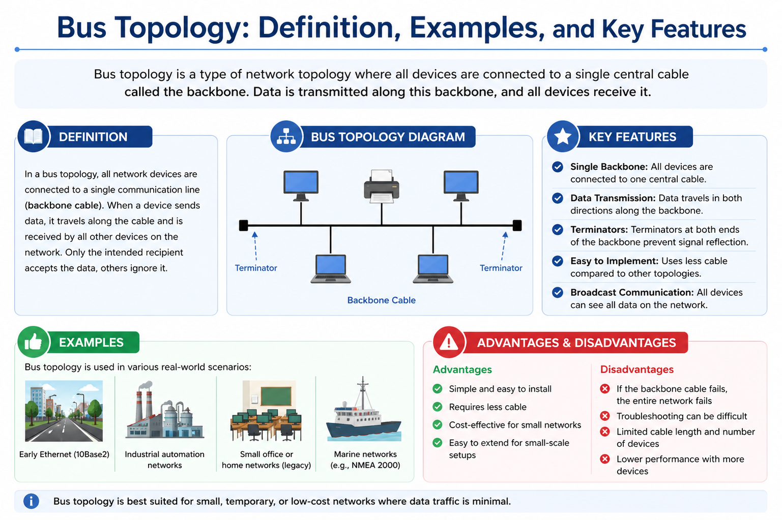
Bus topology is one of the simplest and earliest forms of network design, where all devices are connected to a single communication line. This central line, often referred to as the “bus,” acts as the backbone of the entire network. Every device on the network relies on this shared medium to send and receive data. Because of its straightforward structure, bus topology has historically been a popular choice for small networks, particularly in environments where cost and simplicity are key considerations.
In this configuration, when a device transmits data, the information travels along the bus and becomes available to all connected devices. Each device then examines the data to determine whether it is the intended recipient. If the data is meant for that device, it processes the information; otherwise, it simply ignores it. This method of communication is known as broadcasting and is a defining characteristic of bus topology.
Despite its simplicity, bus topology requires a clear understanding of how network communication works. Concepts such as data transmission, signal flow, and addressing play an important role in ensuring that the system functions correctly. While it may appear basic on the surface, the underlying mechanisms involve coordination among multiple devices sharing a single communication channel.
Understanding Network Topology
To fully grasp bus topology, it is important to first understand the broader concept of network topology. Network topology refers to the physical or logical arrangement of devices within a network. It defines how computers, servers, and other devices are interconnected and how data flows between them.
There are several types of network topologies, each designed to meet different needs. Some focus on efficiency and speed, while others emphasize reliability and fault tolerance. The choice of topology depends on factors such as the size of the network, the available budget, the required performance level, and the physical environment in which the network will operate.
Network topology can be divided into two main categories: physical and logical. Physical topology describes the actual layout of cables and hardware connections, while logical topology explains how data moves through the network regardless of its physical structure. In the case of bus topology, both the physical and logical arrangements are relatively simple, making it easier to understand and implement compared to more complex designs.
Purpose of Bus Topology
The primary purpose of bus topology is to create a simple and efficient network using minimal resources. By connecting all devices to a single communication line, it eliminates the need for complex wiring and additional networking equipment. This makes it an attractive option for small-scale networks where ease of installation and cost-effectiveness are important.
Bus topology is particularly useful in situations where the number of devices is limited and the data traffic is relatively low. In such environments, the shared communication line can handle the transmission demands without significant delays or collisions. The simplicity of the design also allows for quick setup and easy expansion, as new devices can be added by connecting them directly to the bus.
Another important aspect of bus topology is its ability to facilitate straightforward communication between devices. Since all data travels along the same path, there is no need for complex routing or switching mechanisms. This direct approach reduces the overall complexity of the network and makes it easier to manage and maintain.
How Bus Topology Operates
Bus topology operates through a shared communication medium where all devices are connected to a single cable. This cable serves as the pathway for all data transmissions within the network. When a device wants to send data, it places the information onto the bus, and the signal travels in both directions along the cable.
As the data moves through the network, each connected device monitors the signal. Devices check the destination address contained within the data packet to determine whether the information is intended for them. If the address matches, the device accepts and processes the data. If not, it ignores the signal and allows it to continue traveling along the bus.
One important characteristic of bus topology is that it operates in a half-duplex mode. This means that data can travel in both directions, but not simultaneously. Only one device can transmit data at any given time. If multiple devices attempt to send data at the same moment, a collision can occur, leading to transmission errors and delays.
To manage these potential conflicts, networks using bus topology often rely on protocols that control access to the communication medium. These protocols ensure that devices take turns transmitting data, reducing the likelihood of collisions and improving overall network efficiency.
The Role of the Bus in Communication
The bus itself is the most critical component of this topology. It is typically a physical cable, such as a coaxial cable or a twisted pair cable, that connects all devices in a linear arrangement. The quality and condition of this cable directly affect the performance and reliability of the network.
Devices are connected to the bus using connectors, taps, or drop lines. These connections allow each device to access the shared communication medium without disrupting the overall structure of the network. Proper installation and maintenance of these connections are essential to ensure smooth data transmission.
Because all communication relies on a single cable, the bus acts as a central pathway for data flow. This shared medium approach simplifies the network design but also introduces certain limitations. For example, the performance of the network can be affected by the number of connected devices and the amount of data being transmitted.
Broadcast Communication in Bus Topology
Broadcast communication is a fundamental concept in bus topology. When a device sends data, the information is broadcast to all devices connected to the network. This means that every device receives the signal, regardless of whether it is the intended recipient.
Each device is responsible for examining the incoming data and determining whether it should be processed or ignored. This approach ensures that the correct device receives the information while maintaining a simple communication structure.
The broadcast nature of bus topology makes it easy to distribute information across the network. However, it also means that the communication medium can become congested if too many devices are transmitting data. As the network grows, the likelihood of collisions and delays increases, which can impact overall performance.
Key Characteristics of Bus Topology
Bus topology has several defining characteristics that distinguish it from other network configurations. One of the most notable features is the use of a shared communication medium. All devices rely on the same cable for data transmission, which simplifies the network design but also creates a dependency on a single component.
Another important characteristic is the use of termination at both ends of the bus. Terminators are devices that absorb signals and prevent them from reflecting back along the cable. Without proper termination, signal reflections can interfere with data transmission and cause communication errors.
The half-duplex nature of bus topology is also a key feature. Since only one device can transmit data at a time, the network must manage access to the communication medium carefully. This limitation can affect performance, especially in networks with high data traffic.
Bus topology is generally best suited for small networks with limited data requirements. As the number of devices increases, the network becomes more susceptible to collisions, congestion, and performance issues.
Practical Understanding Through Analogy
To better understand how bus topology works, it can be helpful to think of it as a shared communication system. Imagine a group of people in a room using a single microphone connected to a speaker system. When one person speaks into the microphone, everyone in the room can hear the message. However, only the person being addressed will respond, while others simply listen and ignore the message.
In this analogy, the microphone and speaker system represent the bus, while the people in the room represent the devices on the network. Just as only one person can speak at a time to avoid confusion, only one device can transmit data on the bus at any given moment.
This example highlights both the simplicity and the limitations of bus topology. While it provides an easy way to share information, it also requires coordination to prevent conflicts and ensure effective communication.
Importance in Early Networking
Bus topology played a significant role in the early development of computer networks. Its simplicity and low cost made it an ideal choice for small organizations and experimental setups. Many early local area networks were built using this configuration, as it required minimal hardware and was relatively easy to implement.
Over time, as networking technology evolved and the demand for higher performance increased, bus topology became less common. More advanced topologies were developed to address the limitations of the bus design, such as its susceptibility to collisions and its reliance on a single communication line.
Despite its decline in modern networks, bus topology remains an important concept in networking education. Understanding how it works provides valuable insights into the fundamentals of data communication and helps build a foundation for learning more complex network designs.
Physical Components of Bus Topology
Bus topology is built on a set of physical components that collectively enable communication across the network. The most important element is the main cable, commonly referred to as the bus. This cable serves as the backbone of the network, carrying data signals between all connected devices. In earlier implementations, coaxial cables were widely used because of their durability and ability to maintain signal strength over longer distances. In some cases, twisted pair cables have also been used, depending on the network requirements and available infrastructure.
Devices connect to the main cable through connectors such as taps or drop lines. These connectors provide a pathway for individual nodes to access the shared communication medium without breaking the continuity of the bus. Each connection must be secure and properly installed, as even a minor fault in a connector can disrupt communication across the entire network. This dependency on stable connections highlights the importance of careful setup and maintenance in bus topology.
Another critical component is the terminator, which is installed at both ends of the bus cable. The function of the terminator is to absorb signals when they reach the end of the line, preventing them from reflecting back along the cable. Without proper termination, reflected signals can interfere with ongoing transmissions, leading to errors and reduced network efficiency. These physical components together form the structural basis of bus topology and play a key role in its operation.
Signal Transmission and Data Flow
In a bus topology network, data transmission occurs through signals that travel along the central cable. When a device needs to send information, it converts the data into a signal and places it onto the bus. This signal then moves in both directions along the cable, making it accessible to all connected devices.
Each device continuously monitors the bus for incoming signals. When a signal is detected, the device checks the destination address contained within the data packet. If the address matches the device, it processes the information. If not, the signal is ignored and allowed to continue its path along the bus. This process ensures that only the intended recipient responds to the transmitted data, while all other devices remain unaffected.
The shared nature of the communication medium means that devices must coordinate their transmissions. Since only one signal can be transmitted at a time, devices must wait until the bus is free before sending data. This requirement introduces the need for controlled communication, ensuring that signals do not overlap and cause interference. The effectiveness of data flow in bus topology depends on how well this coordination is maintained among devices.
Understanding Data Collisions
Data collisions are a common challenge in bus topology networks. A collision occurs when two or more devices attempt to transmit data at the same time on the shared bus. When this happens, the signals interfere with each other, resulting in corrupted data that cannot be properly interpreted by receiving devices.
To manage this issue, systems often use collision detection methods. When a collision is detected, the devices involved stop transmitting and wait for a short, random period before attempting to resend their data. This approach reduces the chances of repeated collisions and helps maintain the flow of communication within the network.
However, as more devices are added to the network, the likelihood of collisions increases. Frequent collisions can lead to repeated retransmissions, which consume time and reduce overall network efficiency. This limitation makes bus topology less suitable for environments with heavy data traffic or a large number of connected devices.
Bandwidth Limitations and Performance
The performance of a bus topology network is heavily influenced by its available bandwidth. Since all devices share a single communication medium, the total bandwidth must be divided among them. As a result, the more devices connected to the network, the less bandwidth is available for each one.
In networks with minimal data traffic, this limitation may not pose a significant problem. However, in environments where multiple devices frequently transmit data, the shared bandwidth can become a bottleneck. This can lead to slower data transmission speeds and increased delays, especially during peak usage periods.
The length and quality of the bus cable also affect performance. Longer cables can cause signal attenuation, where the strength of the signal weakens as it travels. This can result in slower communication and a higher likelihood of errors. Maintaining proper cable quality and adhering to recommended length limits are essential for ensuring reliable performance in bus topology networks.
Role of Terminators in Stability
Terminators play a crucial role in maintaining the stability of a bus topology network. Positioned at both ends of the bus cable, they are responsible for absorbing signals that reach the end of the line. This prevents signals from reflecting back along the cable and interfering with new transmissions.
Signal reflection can create serious communication problems. When signals bounce back, they can overlap with incoming data, causing confusion and errors in transmission. This can degrade network performance and make it difficult for devices to communicate effectively.
By eliminating signal reflection, terminators help ensure that data flows smoothly and without interference. Their proper installation is essential for maintaining a stable and efficient network. Any issue with a terminator can disrupt the entire system, highlighting its importance in the overall design of bus topology.
Device Connection and Expansion
One of the notable advantages of bus topology is the ease with which devices can be connected or removed. Adding a new device involves simply attaching it to the bus using a connector. This straightforward process allows for quick expansion without requiring significant changes to the existing network structure.
Similarly, devices can be removed without major disruption, provided that the disconnection is handled carefully. This flexibility makes bus topology suitable for environments where the number of devices may change over time.
However, each additional device increases the demand on the shared communication medium. As more devices are connected, the chances of collisions and congestion rise. This means that while expansion is simple, it must be managed carefully to avoid negatively impacting network performance. Balancing the number of devices with the network’s capacity is key to maintaining efficiency.
Error Handling and Reliability
Error handling is an important aspect of bus topology. Because all devices depend on a single communication line, any issue within the network can potentially affect all connected nodes. For example, a damaged cable or a faulty connector can disrupt communication entirely.
To address these challenges, networks often implement error detection mechanisms. These mechanisms check the integrity of transmitted data and identify any corruption that may occur during transmission. If an error is detected, the data is retransmitted to ensure accuracy. While this process improves reliability, it can also introduce delays, particularly in busy networks.
Reliability in bus topology is closely linked to the condition of its physical components. Regular maintenance and monitoring are essential to ensure that the network continues to function properly. Promptly identifying and resolving issues can help prevent widespread disruptions and maintain consistent communication.
Scalability Challenges
Although bus topology is effective for small networks, it faces limitations when it comes to scalability. As the number of connected devices increases, the network becomes more complex to manage. The shared communication medium must handle more data traffic, leading to increased congestion and a higher risk of collisions.
Additionally, the single cable structure creates a dependency that can limit expansion. Extending the network often requires careful planning to ensure that signal strength and performance are not compromised. Beyond a certain point, adding more devices can significantly degrade the network’s efficiency.
These challenges make bus topology less suitable for large-scale networks. While it offers simplicity and cost advantages in smaller setups, its performance can decline as the network grows. Understanding these limitations is essential when deciding whether bus topology is the right choice for a particular application.
Real-World Applications of Bus Topology
Bus topology has been widely used in smaller network environments where simplicity and low cost are more important than high performance. In earlier days of networking, it was common to find this topology in small offices, classrooms, and temporary setups where only a limited number of devices needed to communicate. Its straightforward design made it easy to deploy without requiring advanced technical expertise or expensive equipment.
One of the most practical uses of bus topology has been in temporary network arrangements. For example, in training labs or short-term events, a simple network can be created quickly by connecting devices along a single cable. This approach allows users to share files and communicate without investing in complex infrastructure. The ability to set up and dismantle the network easily makes it highly suitable for such scenarios.
In addition, bus topology has historically been used in early local area networks. Before modern networking equipment became widely available, organizations relied on this design to connect multiple computers within a limited space. Although it is less common today, understanding its real-world applications helps illustrate why it played such an important role in the development of networking technologies.
Use in Educational and Experimental Environments
Bus topology continues to hold value in educational settings, particularly for teaching fundamental networking concepts. Its simple structure makes it an ideal model for demonstrating how data transmission works, how devices communicate, and how network issues such as collisions occur. Students can easily visualize the flow of data along a single cable and understand the challenges associated with shared communication mediums.
In laboratory environments, bus topology is often used for experimentation and demonstration purposes. It allows learners to observe the effects of adding or removing devices, introducing faults, and managing network traffic. These hands-on experiences provide valuable insights into the behavior of networks and help build a strong foundation for understanding more advanced topologies.
Because of its simplicity, bus topology is also useful for testing basic networking equipment. Devices can be connected and evaluated without the need for complex configurations. This makes it a practical choice for controlled environments where the focus is on learning and experimentation rather than large-scale deployment.
Advantages of Bus Topology
Bus topology offers several advantages that make it appealing for specific use cases. One of its most significant benefits is simplicity. The design is easy to understand, implement, and manage, making it accessible even to those with limited networking knowledge. Setting up the network requires minimal components, and the straightforward layout reduces the chances of configuration errors.
Another key advantage is cost-effectiveness. Since all devices share a single communication line, the amount of cabling required is relatively low compared to other topologies. There is no need for additional hardware such as switches or hubs, which helps keep the overall cost of the network down. This makes bus topology an attractive option for small organizations or projects with limited budgets.
Installation is also relatively easy. Devices can be connected directly to the main cable without the need for complex routing or configuration. This plug-and-play approach allows networks to be set up quickly and efficiently. The ease of installation and low cost make bus topology a practical choice for simple networking needs.
Ease of Maintenance and Troubleshooting
Maintaining a bus topology network can be straightforward due to its simple structure. With only one main cable and a limited number of connections, it is often easier to identify and resolve issues compared to more complex topologies. When a problem occurs, network administrators can focus on the central cable and its connections to locate the source of the issue.
Troubleshooting is also simplified because the network layout is linear. This makes it easier to trace the path of data and identify where disruptions may be occurring. For example, if a device is not receiving data, the issue can often be traced back to a specific section of the cable or a faulty connector.
However, while troubleshooting may be easier in some cases, it is important to note that certain issues can have widespread effects. A problem with the main cable can impact all devices on the network, making it critical to address such issues quickly to restore normal operation.
Limitations of Bus Topology
Despite its advantages, bus topology has several limitations that restrict its use in modern networks. One of the most significant drawbacks is its reliance on a single communication line. If the main cable fails, the entire network becomes inoperable. This single point of failure makes bus topology less reliable compared to other designs that offer redundancy.
Another limitation is the risk of data collisions. Since all devices share the same communication medium, simultaneous transmissions can lead to conflicts and data loss. As the number of devices increases, the likelihood of collisions also rises, which can significantly impact network performance.
Bus topology is also limited in terms of scalability. While it is easy to add devices, doing so increases the load on the network and can lead to congestion. This makes it unsuitable for large networks with high data traffic, where more advanced topologies are required to maintain performance and reliability.
Network Congestion and Latency Issues
As more devices are added to a bus topology network, the shared communication medium can become congested. Each device must wait for its turn to transmit data, which can lead to delays, especially in networks with high levels of activity. This congestion can reduce the overall efficiency of the network and affect the user experience.
Latency is another issue associated with bus topology. Latency refers to the time it takes for data to travel from the sender to the receiver. In a busy network, devices may experience delays as they wait for access to the bus. Additionally, collisions and retransmissions can further increase latency, making communication slower and less efficient.
These performance challenges highlight the importance of carefully managing the number of devices and the volume of data in a bus topology network. Without proper management, congestion and latency can significantly impact the effectiveness of the network.
Impact of Cable Damage on Network Functionality
The integrity of the main cable is crucial to the operation of a bus topology network. Any damage to the cable can disrupt communication for all connected devices. This could include physical damage such as cuts or breaks, as well as issues like loose connections or faulty connectors.
When the cable is damaged, signals may not be able to travel effectively along the bus. This can result in partial or complete loss of communication, depending on the severity of the issue. In some cases, only a portion of the network may be affected, while in others, the entire system may go offline.
Because of this dependency on a single cable, maintaining its condition is essential. Regular inspections and proper handling can help prevent damage and ensure that the network continues to function reliably. Promptly addressing any issues that arise is also critical to minimizing downtime and maintaining communication.
Relevance in Modern Networking Concepts
Although bus topology is rarely used in modern large-scale networks, its concepts continue to influence current networking designs. Understanding how data is transmitted over a shared medium provides valuable insights into the challenges of network communication, such as collisions, congestion, and bandwidth limitations.
Many modern topologies have evolved to address the limitations of bus topology while retaining some of its fundamental principles. For example, the idea of a shared communication medium can still be seen in certain network technologies, although it is often managed more efficiently using advanced protocols and hardware.
Studying bus topology helps build a strong foundation for understanding these modern systems. By learning about its strengths and weaknesses, network professionals can make more informed decisions when designing and managing networks. This knowledge remains relevant even as technology continues to evolve.
Comparison with Other Network Topologies
Bus topology can be better understood when compared with other common network designs. Each topology has its own structure, advantages, and limitations, making it suitable for different scenarios. In contrast to bus topology, a star topology connects all devices to a central hub or switch. This central device manages communication and ensures that data is sent directly to the intended recipient rather than being broadcast to all devices. This reduces the chances of collisions and improves overall performance, especially in larger networks.
Another commonly used design is ring topology, where each device is connected to two others, forming a circular structure. Data travels in a specific direction from one device to the next until it reaches its destination. This method eliminates collisions but introduces complexity in setup and maintenance. A failure in one part of the ring can also disrupt the entire network unless additional mechanisms are in place.
Mesh topology represents a more advanced approach, where every device is connected to multiple other devices. This creates multiple paths for data transmission, ensuring high reliability and fault tolerance. However, this level of connectivity requires a significant amount of cabling and configuration, making it more expensive and complex than bus topology.
Tree topology combines elements of both bus and star designs. It consists of multiple star networks connected to a central backbone, which often resembles a bus. This hybrid approach allows for better scalability and organization, making it suitable for larger networks. By comparing these topologies, it becomes clear that bus topology prioritizes simplicity and cost, while other designs focus on performance, reliability, and scalability.
Security Considerations in Bus Topology
Security is an important factor in any network design, and bus topology presents unique challenges in this area. Because all data is broadcast across the network, every connected device has access to the transmitted information. Although devices are programmed to ignore data not intended for them, the broadcast nature of the system can make it easier for unauthorized users to intercept sensitive information.
This lack of inherent security makes bus topology less suitable for environments where data privacy is a priority. Additional security measures, such as encryption and access controls, may be required to protect information. However, implementing these measures can add complexity to a system that is otherwise designed to be simple.
Another concern is the potential for unauthorized devices to connect to the network. Since adding a device is relatively easy, it may be difficult to control who has access to the network without proper monitoring and management. This highlights the importance of maintaining strict control over physical access to the network infrastructure.
Maintenance and Long-Term Viability
Maintaining a bus topology network requires careful attention to its physical components. The main cable, connectors, and terminators must all be kept in good condition to ensure reliable operation. Regular inspections can help identify issues such as wear and tear, loose connections, or damage that could disrupt communication.
Over time, the limitations of bus topology become more apparent, particularly as network demands increase. Modern applications often require higher speeds, greater reliability, and improved scalability than bus topology can provide. As a result, many organizations have transitioned to more advanced network designs that better meet these requirements.
Despite this shift, understanding how to maintain a bus topology network remains valuable, especially in environments where it is still in use. Proper maintenance practices can extend the lifespan of the network and ensure that it continues to function effectively within its intended scope.
Transition to Modern Networking Solutions
As technology has evolved, the need for more efficient and reliable networking solutions has led to the decline of bus topology in modern environments. Newer topologies, such as star and mesh, offer significant improvements in terms of performance, scalability, and fault tolerance. These designs address many of the limitations associated with bus topology, making them more suitable for today’s complex networking needs.
The transition from bus topology to modern solutions often involves replacing the shared communication medium with dedicated connections and advanced networking devices. This shift allows for faster data transmission, reduced collisions, and improved overall efficiency. While this transition may require additional investment, the benefits in terms of performance and reliability are substantial.
Even though bus topology is no longer widely used in large-scale networks, its influence can still be seen in certain aspects of modern networking. The concept of a shared communication medium, for example, continues to be relevant in specific technologies, although it is now managed more effectively باستخدام advanced protocols and hardware.
When Bus Topology Is Still Useful
Although bus topology has largely been replaced in modern networks, it still has practical applications in certain situations. Small, temporary networks with limited data requirements can benefit from its simplicity and low cost. For example, it may be used in testing environments, small labs, or short-term setups where advanced infrastructure is not necessary.
In such cases, the ease of installation and minimal hardware requirements make bus topology a convenient choice. It allows users to quickly establish a network without the need for complex configuration or expensive equipment. However, it is important to recognize its limitations and ensure that it is used in scenarios where its drawbacks will not significantly impact performance.
Understanding when to use bus topology is just as important as understanding how it works. By selecting the appropriate topology for a given situation, network designers can achieve a balance between simplicity, cost, and performance.
Conclusion
Bus topology represents one of the most fundamental concepts in computer networking. Its simple design, based on a single shared communication line, provides an easy way to connect multiple devices and enable data exchange. This simplicity made it a popular choice in the early days of networking, particularly for small and cost-sensitive environments.
Throughout its operation, bus topology demonstrates key networking principles such as broadcast communication, shared bandwidth, and collision management. These concepts remain important for understanding how networks function, even as technology continues to advance. At the same time, the limitations of bus topology, including its susceptibility to collisions, limited scalability, and dependence on a single cable, highlight the need for more advanced solutions in larger and more demanding environments.
While it is no longer the preferred choice for modern networks, bus topology still holds educational and practical value. It serves as a foundation for learning about network design and provides insight into the evolution of networking technologies. By studying its strengths and weaknesses, individuals can develop a deeper understanding of how to design efficient and reliable networks that meet the needs of today’s digital world.